Thursday, December 6, 2018

Week of 12/5/2018

12/5/2018                                                                  Akash Sandhu

The team is working towards  finishing the final report for the deadline of December 17th. During the group session, the team presentations were continued. After the team presentations, the team was able to update both Dan and Ethan on the  current progress of the team. Dan was able to provide some helpful suggestions and advise for the designs. Dan suggested that for the guide arm, the tubing be bought instead of manufactured. Lastly, Dan suggested I also change the mounting a little.

Friday, November 30, 2018

Week of 11/28/2018

Week of 11/28/2018                                                Akash Sandhu

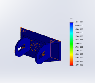
The guide arm design and assembly is complete. The mounted points have been added to both the drive and slave bogie guide arm. The last FEA was also completed for the slave bogie guide arm as show below. There are confirmed mounting points on the slave bogie. There still need to be mounting points made on the drive bogie. The goal is to finish up the report, and the bill of materials. The goal when the semester ends is to start working on Engineering drawings.
Factor of Safety = 3.321

Factor of Safety = 3.659

Monday, November 26, 2018

Week of 11/21/2018

Week of 11/21/2018                                                                                                       Akash Sandhu   
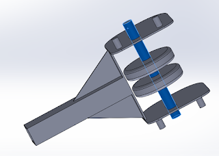
 For the guide arm, the mounting points on the guide arm were also created for the slave bogie. They have been test fitted on slave bogie assembly. However, they need to be test fitted on the final slave bogie design that the interaction team is working on. The image of the test fitted guide arm on the slave bogie is provided below. The goal of upcoming week is report and presentation. The both the guide arms still need to be tested on the curved section of the track.


Figure 1: This image show the guide arm attached to the slave bogie.

Sunday, November 18, 2018

11/14/2018                                                                                                                        Akash Sandhu

Guide Arm
I have added mounting points to the guide arm for the drive bogie, and have tested that it fits the drive bogie. Now the interaction team needs to add mounting points to the drive bogie. Last, there was also focus on completing the last individual writing assignment. The goal is to determine mounting points for the slave bogie next. FEA was also completed on the guide arm with these new mounting points, and two different loading scenarios were tested. The F.o.S was 2.8 for one scenario and 4.4 for the other.


Wednesday, November 7, 2018

Week 11/7/2018

Week 11/17/2018                                                                 Guide Arm (Akash Sandhu)

       For the guide arm, I was facing two problems. As discussed in Presentation 2, the exact spring I had designed and calculated for was not available at McMaster-Carr, so I had to adapt my design and redo my calculations with the new spring. When I redesign the spring load wheel holder with the new slot dimensions, the slot came in the way the spring was compressed all the way. To accommodate the problem, I decrease the total amount the wheel was allowed to move, and then I to make changes to the new arm of the guide-arm. The new guide-arm was also designed this week. Furthermore, the spring will be pre-loaded even when going down straight stretches of the track. Lastly, I am also working on the last individual writing assignment which is due next week.


Thursday, November 1, 2018

Week of 10/31/2018

Individual blog- Akash Sandhu-10/31/2018

Guide Arm:
  • currently working on improving on the design for the spring holder and wheel holder
    • the Safety factor is really high attempting to decrease material and make design changes to improve design and optimize for safety of factor above 2, but not extremely high.
    • images of the components are provided that show area where material can be removed.
    • furthermore, the prototype should a concern a different loading concern when it comes off of switching tracks, the force will not all be perpendicular to the track, so additionally FEA was done with different loading conditions.
      • minimum Factor of safety = 27
  • goals for next week
    • start report
    • Redesign my initial design of the "arm" for the guide arm,
      • and hopefully have confirmed mounting points from interaction team.


Figure 1: The blue areas shows where most of the load is acting.

Figure 2: The transparent areas show where material can be taken off.

Figure 3: The loading was changed for this FEA study of the part.

Thursday, October 25, 2018

Week of 10/25/2018

10/25/2018                                                                                                            Akash Sandhu
For this week, we worked on 3D printing the design of the main component of the spring loaded guide arm. Pictures of the rapid prototype are provided below; the prototype is half-scale. From the damper calculations, I also contacted a possible vendor to obtain information about cycles/min. I also performed FEA on the last week's design, and changed dimensions so it can fit inside the 12 cm gap of the tracks. The parts has a low factor of safety, just above 1. I went back redesigned the wheel and spring holder.  I relocated mounting points, add ribs, and increased material on the new design iteration. This increases safety factor to 2 for one component, and 10 for the other. Pictures are located below.


Thursday, October 18, 2018

Week 10/18/2018

Akash Sandhu                                                                                                                   10/18/2018

Spring Loaded Guide Arm.
In preparing for the presentation I performed calculations for max load the spring needs to handle and spring rate. I also researched for the damper criteria need for damper selection. I research the the wavelength for roughness/straightness of light rail tracks. Then I went on to calculated the frequency need for the damper and the Max energy absorbed. The natural frequency of the guide arm assembly is much lower than the frequency of force given by the track. Looking at my calculated information for the damper Dr. Furman than concluded that the damper would not be practical or cost-efficient for the maker-faire model. Nevertheless, I will still continue designing for damper, but it will not be included in manufactured design. It was confirmed with the guide-way team that the track gap distance will remain the same at 12 cm. So currently, I am working to redesigning the whole design to be smaller using smaller wheels. While redesigning, I am taking into account my FEA results from previous design version. The plan is to 3d print the spring loaded component for rapid prototyping. Below I have attached some of the CAD designs and my MATLAB calculations.

ME 195a Spring loaded guide Arm calculations

Akash Sandhu

Contents

Force calculations

M = 500:100:7000; % kg, weight of whole bogie and loaded podcar
total_length = length(M)-1;
% v_min = 2;
% v_max = 20;
% dt_v = (v_max-v_min)/total_length;
%
% v = v_min:dt_v:v_max  % m/s, operating speed of bogie
v = 1 % m/s
r_min = 8;
r_max = 50;
dt_r = (r_max-r_min)/total_length;
r = r_min:dt_r:r_max;   % m,   smallest radius

for i = 1:length(M)
    for j = 1:length(r)
        f(i,j) = 2*((M(i)*v^2)/r(j));
    end
end
figure(1);
surf(M,r,f);
xlabel('Mass [kg]');
ylabel('Radius [m]');
zlabel('Force [N]');
title('Force vs Curvature and Mass');
v =

     1

Spring Calculations

clear all; clc;
M_tot = 2000 +300; %[kg]
M_eq = M_tot/3;
x = .13; % [m]
v = 1; % [m/s] about 2 mph
r = 8; %[m] radius of curve
F = 2*((M_eq*v^2)/r); % [N]
fprintf('The force acting on each spring is %1.3f N\n ',F)
k = F/x; %[N/m]
fprintf('The Spring rate is %1.3f N/m \n',k)
The force acting on each spring is 191.667 N
 The Spring rate is 1474.359 N/m 

Damper (Shock Absorber) Calculations

F = 2*((M_eq*v^2)/r); % [N]
M_tot = 2000 + 300; %[kg] pod + bogie
M_eq = M_tot/3; % [kg]
v_y = 13; % [m/s] speed going straight
L = 0.016;% [m] stroke of damper
theta_deg = 13; % [degree] angle of curvature
theta = theta_deg*(pi/180); % [rad]
v_x = tan(theta)*v_y; %[m/s] speed at impact
FS = 2; % factor of safety
E_1 = 0.5*M_eq*v_x^2;
E_2 = F*L;
E_tot = E_1+E_2;
E_max = FS*E_tot; %[Nm] max energy absorbed
fprintf('The max energy the damper needs to absorb is %1.3f Nm\n',E_max);

wavelength = 0.05; %[m] irregularities observed at
freq = v_y/wavelength; % [Hz]
fprintf('The forcing frequency from the track irregularities will be %1.3f Hz\n', freq);
freq = freq*60; % [ cycles/min]
fprintf('The damper will need to be able to do %1.3f cycles/min\n',freq);
The max energy the damper needs to absorb is 6912.052 Nm
The forcing frequency from the track irregularities will be 260.000 Hz
The damper will need to be able to do 15600.000 cycles/min

Thursday, October 11, 2018

Week of 10/10/2018

Week of 10/10                                                                                          Akash Sandhu


For this previous, I worked on some problems on the design I created. These problem came across when I trying running FEA. This week I fixed some mating issue I was having with the slot which would not allow me FEA. Furthermore, Dr. Furman had recommended, during office hours, to incorporated dampers into the guide arm, to reduce vibrations of the spring. This week I began looking at damper. However, I have come across two problem; I do not know exactly how the mounting hardware works for dampers, and I am trying to find the a way to do calculations to pick the correct damper. Also, I did some consideration of the forces that would be acting on the guide-arm wheels and spring, and Dr. Furman and I concluded only centripetal force needs to considered. I then went and created a MATLAB 3-D plot which is attached below. I was also able to complete the FEA on the part with 2000 N force to see area of concern. Lastly, the design is a little to big for the current with so I decided to go with smaller wheels to accommodate for the clearance problem; Nevertheless, now the design will change in dimension due to smaller wheels.

Thursday, October 4, 2018

Week of 10/4/2018

Week 10/4/ 2018                                                                                                               Akash Sandhu
During the team meeting, I learned how some basics of performing FEA using Guide Arm. Also, I considered with the team the forces that need to be considered for further analysis. Also, I worked on the first individual writing assignment. I was also introduced to a Tuned Mass Damper (TMD), which could help eliminate the vibration of the arm of the guide arm system. Also, Joshua and I attended ANSYS seminar and were introduced new ways of optimizing designs. During the FEA, I came across some problems on the second design of the guide arm, so I might have to redesign the whole concept. A more detailed study is need to solve the problems in the design. There was also discussions for rapid prototyping; the goal will be to use 3D- printer.

Friday, September 28, 2018

Week of 9/26/2018

The highlight of last week and this week was preparing for Presentation 1. I work on the guide arm of the bogie. Dan recommends in his final report from Spring 2018 that the guide arm should be spring loaded. The main benefits it to reduces wear on wheels of bogie and vibrations endured by the whole bogie. The main purpose of the guide arm is to guide the bogie around curved sections of the track. For the presentation, I presented two idea of how plan to make the wheels of the guide arm spring loaded. I have attached both the designs below. Also, the team is responsible  providing the Motor team with mounting points for the hub motor axles. I did some research on bicycle hub motors, and came across a peer-review articles that suggests a new method of mounting hub motors to the forks of the bicycle. The gist of the article is to use an elongated axles that threads into the sleave pressed in the motor; on the other side, a cap then tightens into the axle. A cut-out of the article is also provided below.


Sunday, September 9, 2018

Week of 9/5/2018

Akash Sandhu -Member of Full-Scale Drivetrain
Week of 9/5/2018 
Lightning Presentation and Proposal
One of the main task that were completed this week was the "Lightning Presentation". For my part of the "Lightning Presentation". I had done my research of what torque vectoring, the benefits of torque vectoring, and methods of application. I learned that torque vectoring is vehicles purposely transfer different amounts of power to different axles of the vehicle or an individual wheel. Initial, torque vectoring was only done on 4 wheel drive vehicles where the drive train of the car would change the power distribution between the front and rear axles of the vehicle when sensing slippage. However, the technique of torque vectoring has improved over the years where vehicles are now able to control how much power an individual driving wheel receives. This has allowed both front and rear wheel drive vehicles to implement torque vectoring. It has be shown to be helpful in increasing performance of vehicles in cornering. Furthermore, it helps to deal with wheel slippage. However, after discuss this with Dr. Furman, it does not seem reasonable and cost efficient to implement this kind of system into the bogie. The next task of the week was completing the proposal of the full-scale drive-train team.  For the proposal, I worked on the project description, project objectives, the outline for scope. Furthermore, I contributed some to of the deliverables, such as the need for another motor if the High density motor does not work. I also contributed a little to the required facilities and funding, and the general formatting of the proposal.

Saturday, August 11, 2018

Introduction- Akash Sandhu

Akash Sandhu
email: akashpreet12@gmail.com
phone #: (209) 581-1014


I am going to be a senior the upcoming semester as a mechanical engineering student, and my goal is to graduate next year in May. My interests are to watch sports, and TV shows when I'm not studying. I am interested in the automated transit system for many reasons. However, one of the main reasons is to help solve the problem of growing traffic in developing urban cities. Secondly, this new system of transit provides a safer method of transits for humans which is important. The mistake one driver makes on the road can lead to injuring many, and an automated public transit system can help in avoiding this problem.