Akash Sandhu 10/18/2018
Spring Loaded Guide Arm.
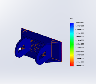
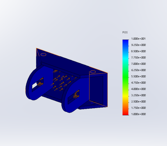
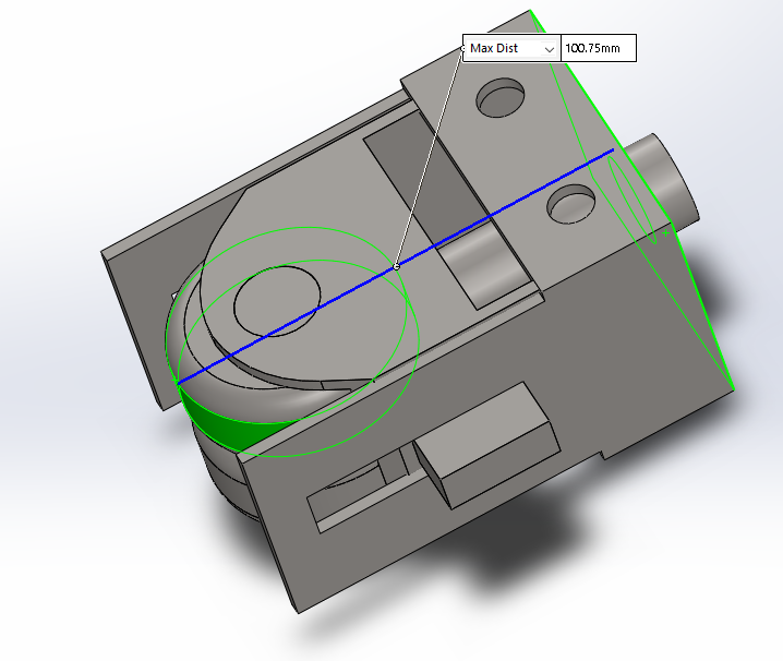
In preparing for the presentation I performed calculations for max load the spring needs to handle and spring rate. I also researched for the damper criteria need for damper selection. I research the the wavelength for roughness/straightness of light rail tracks. Then I went on to calculated the frequency need for the damper and the Max energy absorbed. The natural frequency of the guide arm assembly is much lower than the frequency of force given by the track. Looking at my calculated information for the damper Dr. Furman than concluded that the damper would not be practical or cost-efficient for the maker-faire model. Nevertheless, I will still continue designing for damper, but it will not be included in manufactured design. It was confirmed with the guide-way team that the track gap distance will remain the same at 12 cm. So currently, I am working to redesigning the whole design to be smaller using smaller wheels. While redesigning, I am taking into account my FEA results from previous design version. The plan is to 3d print the spring loaded component for rapid prototyping. Below I have attached some of the CAD designs and my MATLAB calculations.


ME 195a Spring loaded guide Arm calculations
Akash Sandhu
Contents
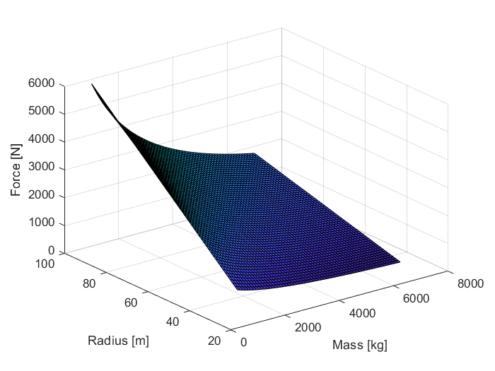
Force calculations
M = 500:100:7000;
total_length = length(M)-1;
v =

     1
r_min = 8;
r_max = 50;
dt_r = (r_max-r_min)/total_length;
r = r_min:dt_r:r_max;
for i = 1:length(M)
for j = 1:length(r)
f(i,j) = 2*((M(i)*v^2)/r(j));
end
end
figure(1);
surf(M,r,f);
xlabel('Mass [kg]');
ylabel('Radius [m]');
zlabel('Force [N]');
title('Force vs Curvature and Mass');
v =
1

Spring Calculations
clear all; clc;
M_tot = 2000 +300;
M_eq = M_tot/3;
x = .13;
v = 1;
r = 8;
F = 2*((M_eq*v^2)/r);
fprintf('The force acting on each spring is %1.3f N\n ',F)
k = F/x;
fprintf('The Spring rate is %1.3f N/m \n',k)
The force acting on each spring is 191.667 N
 The Spring rate is 1474.359 N/m
Damper (Shock Absorber) Calculations
F = 2*((M_eq*v^2)/r);
M_tot = 2000 + 300;
M_eq = M_tot/3;
v_y = 13;
L = 0.016;
theta_deg = 13;
theta = theta_deg*(pi/180);
v_x = tan(theta)*v_y;
FS = 2;
E_1 = 0.5*M_eq*v_x^2;
E_2 = F*L;
E_tot = E_1+E_2;
E_max = FS*E_tot;
fprintf('The max energy the damper needs to absorb is %1.3f Nm\n',E_max);
wavelength = 0.05;
freq = v_y/wavelength;
fprintf('The forcing frequency from the track irregularities will be %1.3f Hz\n', freq);
freq = freq*60;
fprintf('The damper will need to be able to do %1.3f cycles/min\n',freq);
The max energy the damper needs to absorb is 6912.052 Nm
The forcing frequency from the track irregularities will be 260.000 Hz
The damper will need to be able to do 15600.000 cycles/min