Guide Arm Akash Sandhu
As mentioned last week, I had completed all of the manufacturing last week; however, there was a little bit of a mounting issue. Nevertheless, I was able to mount finish the mounting for all of the arms Tuesday. On Wednesday, professor Furman conducted a prototype evaluation. Furthermore, the team and I went to Alumni night, which helped be more prepared for questions I might be asked during my final presentation. It was also a great opportunity to showcase my design. I also focused on the final presentation on Friday (5/10).
Sunday, May 12, 2019
Saturday, May 4, 2019
Week of 5/1/2019
Akash Sandhu 5/1/2019
The goal of this week was to have all manufacturing completed for all three of the guide arms and to test fit the guide arms onto the bogies. All of the guide arms assemblies are completed. I attempted to test fit the slave bogie guide arm and was faced with some small aligning problems. However, I have solve the problem and have successfully attached one of the guide arms to the slave bogie. The other slave bogie is also ready to be attached to the slave bogie. The drive bogie guide arm is complete, but the interaction team did not have ready as of early Friday morning for me to attach my arm. There should be no problems with the drive bogie as long as the physical bogie matches the CAD model.
I have also weighed the arms, they are well below the 15 kg limit.
The goal of this week was to have all manufacturing completed for all three of the guide arms and to test fit the guide arms onto the bogies. All of the guide arms assemblies are completed. I attempted to test fit the slave bogie guide arm and was faced with some small aligning problems. However, I have solve the problem and have successfully attached one of the guide arms to the slave bogie. The other slave bogie is also ready to be attached to the slave bogie. The drive bogie guide arm is complete, but the interaction team did not have ready as of early Friday morning for me to attach my arm. There should be no problems with the drive bogie as long as the physical bogie matches the CAD model.
I have also weighed the arms, they are well below the 15 kg limit.
Wednesday, April 24, 2019
Week 4/24/2019
Akash Sandhu 4/24/2019
I have found a welding shop that gave a cheaper quote ($250) compared to the initial quote by Nam's Welding. He has already tack welded half my parts and the plan is to finish the rest of the welding on Friday. I have provided the images below. Furthermore, I aim to be test fitting my parts to the slave bogie.
Week of 4/17/2019
Akash Sandhu
Guide Arm
I have prepped all of my parts for welding. I was having trouble getting welding done at central shop and getting access to MIG welder. I have gotten one spring-wheel assembly welded for free, but that person is not willing to do anymore. I have got another lead (Quiet Horsepower) local to me in Newark willing to weld the rest of the parts and the quote is $250. I should have my parts complete by this upcoming Friday (4/26).
Guide Arm
I have prepped all of my parts for welding. I was having trouble getting welding done at central shop and getting access to MIG welder. I have gotten one spring-wheel assembly welded for free, but that person is not willing to do anymore. I have got another lead (Quiet Horsepower) local to me in Newark willing to weld the rest of the parts and the quote is $250. I should have my parts complete by this upcoming Friday (4/26).
Sunday, April 14, 2019
Week of 4/10/2019
Week of 4/10/2019
This week the focus was on both the presentation and manufacturing of components for the guide arms. I have passed the safety quiz for room 123 which gives me access to central shop. I have finished cutting the slot runner tabs and milled down the spacers. Also, I had my MIG welding training on Friday where I had my teammates join me also. However, I was not as proficient at welding as I hoped I would be. I am currently investigating alternative solutions. I have also cut the square tubing needed for the drive arm.
The goal for next week is to cut out spring holder tabs, and square tubing for both the slave bogie guide arms. Additionally, the goal is to have all my parts prepared for welding (cleaning the rust of the components). Furthermore, I plan to start welding this week
This week the focus was on both the presentation and manufacturing of components for the guide arms. I have passed the safety quiz for room 123 which gives me access to central shop. I have finished cutting the slot runner tabs and milled down the spacers. Also, I had my MIG welding training on Friday where I had my teammates join me also. However, I was not as proficient at welding as I hoped I would be. I am currently investigating alternative solutions. I have also cut the square tubing needed for the drive arm.
The goal for next week is to cut out spring holder tabs, and square tubing for both the slave bogie guide arms. Additionally, the goal is to have all my parts prepared for welding (cleaning the rust of the components). Furthermore, I plan to start welding this week
Monday, April 8, 2019
Week 3/27/2019-4/5/2019
Akash Sandhu
I have passed my the MakerSpace Safety Quiz, and Dr. Furman helped with machining my tabs. Over the spring break, I only had access to the Superway mill and lathe for one day because Makerspace was closed, so we were only allowed inside with an adviser or Daniel (member of wayside). I was able to lathe down the radius of a steel rod and then use a horizontal saw to cut to size. Also over the break, I dropped off material for water jet cutting at the Central shop and got it back. I also got the material back over the break; I have done an inventory of the parts. Also I have completed the MakerSpace welding module; however, I went to take the quiz and there is no question inside of it. I have also been preparing material for the second presentation. Going forward, the priorty is to gain access to welding as soon as possible, hopefully by end of this week. Otherwise there can be a delay in manufacturing.
Friday, March 22, 2019
Week of 3/20/2019
Week of 3/20/2019
Previously, for the drive bogie guide arm, the location of the mounting onto the drive bogie was confirmed. However, this week I added holes on the integration teams design helping to INTEGRATE the guide arm to the drive bogie. This week essay 2 is due, so I am working to finish of the assignment for this week.
Thursday, March 14, 2019
Week of 3/14/2019
Week of 3/14/2019 Akash Sandhu
The focus of last week was to prepare and give the presentation. Also, the focus was to send out the order to Central shop and get a ticket number for the order to get put into the work Queue for the water jet. The order was sent out with an email to Kyle at the Central Shop, and are waiting to hear back. For the guide are there are some items which I need to mill and Lathe. I need to mill out some slut-runner tabs, and lathe a rod to get the correct outer-diameter. Additionally, McMaster-Car did not have the exact size spacers I needed, so the plan is to mill those parts as well. I am preparing to take the general safety quiz for the MakerSpace and should have that complete before next week, so I can start milling. I will also need access to ME41 tech shop, so the plan is to visit the ME department to obtain access this Friday.
Saturday, March 9, 2019
Week of 2/27-3/6
Week of 2/27-3/6 Akash Sandhu
I have bought all of the material, which included both the metal stock and McMaster-Car parts. The receipts of these orders have also been handed over to Tynan. Also, I have combined Josh's and my parts together for water jet. I have both emailed and created a job ticket for the central shop. This also means that I have completed my 2D engineering drawings of my parts. Also, I had a manufacturing issue for the slot-runner, but now I have simplified the slot design for increased ease of manufacturing. The goal is to start working on milling the tabs next week, and to complete general safety quizzes for MakerSpace. I have also attended training for waterjet at MakerSpace.
Wednesday, February 27, 2019
Week of 2/22/2019
Week of 2/22/2019 Akash Sandhu
The focus was gather material for my guide-arm. The team then went Sims to see which materials were available. The have low-carbon steel sheets which are easy to weld in sections of 2'x4', 4'x4', and 4'x'6. No material was bought yet. Furthermore, I am focusing on making drawings of my guide arm. This turns out be time consuming because I have to split my design to break the design into pieces of 3 mm thick sheet metal. I have estimated the total material I will need using solidworks. I created a simplified template of how my parts would fit, which concludes I need a 3'x3' steel sheet.
The template is provided below.
The focus was gather material for my guide-arm. The team then went Sims to see which materials were available. The have low-carbon steel sheets which are easy to weld in sections of 2'x4', 4'x4', and 4'x'6. No material was bought yet. Furthermore, I am focusing on making drawings of my guide arm. This turns out be time consuming because I have to split my design to break the design into pieces of 3 mm thick sheet metal. I have estimated the total material I will need using solidworks. I created a simplified template of how my parts would fit, which concludes I need a 3'x3' steel sheet.
The template is provided below.
Tuesday, February 19, 2019
Week of 2/13/2019 Update
Akash Sandhu Week of 2/13/2019 Update
After the move into the new location and changes in the plan for the track. There persisted the question of whether I needed to make changes to my design from last semester. On February 13, I spoke with both the guide way team and interaction team. The dependencies of my design are on the distance between the track and the mounting points on the slave and drive bogie. After consulting the team, it was confirmed the track gap will remain at 12 cm and the mounting points are going to be the same.
The goal of this semester is to manufacture and test our designs. To get start, my bill of materials is mostly done. I have selected the wheels for my design; however, McMaster-Car did not have the exact wheels the designed needed, so I had to change my design. I changed some dimensions, and decrease the number of wheels needed for the design. Furthermore, I have found the steel tubing on McMaster-Car for my design, again it is not to my dimensions. Springs were selected from last semester. Main item still needed is 3 mm sheet metal for water jet cutting.
After the move into the new location and changes in the plan for the track. There persisted the question of whether I needed to make changes to my design from last semester. On February 13, I spoke with both the guide way team and interaction team. The dependencies of my design are on the distance between the track and the mounting points on the slave and drive bogie. After consulting the team, it was confirmed the track gap will remain at 12 cm and the mounting points are going to be the same.
The goal of this semester is to manufacture and test our designs. To get start, my bill of materials is mostly done. I have selected the wheels for my design; however, McMaster-Car did not have the exact wheels the designed needed, so I had to change my design. I changed some dimensions, and decrease the number of wheels needed for the design. Furthermore, I have found the steel tubing on McMaster-Car for my design, again it is not to my dimensions. Springs were selected from last semester. Main item still needed is 3 mm sheet metal for water jet cutting.
Thursday, December 6, 2018
Week of 12/5/2018
12/5/2018 Akash Sandhu
The team is working towards finishing the final report for the deadline of December 17th. During the group session, the team presentations were continued. After the team presentations, the team was able to update both Dan and Ethan on the current progress of the team. Dan was able to provide some helpful suggestions and advise for the designs. Dan suggested that for the guide arm, the tubing be bought instead of manufactured. Lastly, Dan suggested I also change the mounting a little.
Friday, November 30, 2018
Week of 11/28/2018
Week of 11/28/2018 Akash Sandhu
The guide arm design and assembly is complete. The mounted points have been added to both the drive and slave bogie guide arm. The last FEA was also completed for the slave bogie guide arm as show below. There are confirmed mounting points on the slave bogie. There still need to be mounting points made on the drive bogie. The goal is to finish up the report, and the bill of materials. The goal when the semester ends is to start working on Engineering drawings.
Factor of Safety = 3.321
Factor of Safety = 3.659
Monday, November 26, 2018
Week of 11/21/2018
Week of 11/21/2018 Akash Sandhu
For the guide arm, the mounting points on the guide arm were also created for the slave bogie. They have been test fitted on slave bogie assembly. However, they need to be test fitted on the final slave bogie design that the interaction team is working on. The image of the test fitted guide arm on the slave bogie is provided below. The goal of upcoming week is report and presentation. The both the guide arms still need to be tested on the curved section of the track.
Figure 1: This image show the guide arm attached to the slave bogie.
For the guide arm, the mounting points on the guide arm were also created for the slave bogie. They have been test fitted on slave bogie assembly. However, they need to be test fitted on the final slave bogie design that the interaction team is working on. The image of the test fitted guide arm on the slave bogie is provided below. The goal of upcoming week is report and presentation. The both the guide arms still need to be tested on the curved section of the track.
Sunday, November 18, 2018
11/14/2018 Akash Sandhu
Guide Arm
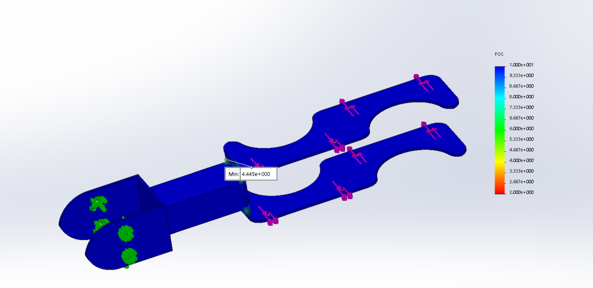
I have added mounting points to the guide arm for the drive bogie, and have tested that it fits the drive bogie. Now the interaction team needs to add mounting points to the drive bogie. Last, there was also focus on completing the last individual writing assignment. The goal is to determine mounting points for the slave bogie next. FEA was also completed on the guide arm with these new mounting points, and two different loading scenarios were tested. The F.o.S was 2.8 for one scenario and 4.4 for the other.
Guide Arm
I have added mounting points to the guide arm for the drive bogie, and have tested that it fits the drive bogie. Now the interaction team needs to add mounting points to the drive bogie. Last, there was also focus on completing the last individual writing assignment. The goal is to determine mounting points for the slave bogie next. FEA was also completed on the guide arm with these new mounting points, and two different loading scenarios were tested. The F.o.S was 2.8 for one scenario and 4.4 for the other.
Wednesday, November 7, 2018
Week 11/7/2018
Week 11/17/2018 Guide Arm (Akash Sandhu)
For the guide arm, I was facing two problems. As discussed in Presentation 2, the exact spring I had designed and calculated for was not available at McMaster-Carr, so I had to adapt my design and redo my calculations with the new spring. When I redesign the spring load wheel holder with the new slot dimensions, the slot came in the way the spring was compressed all the way. To accommodate the problem, I decrease the total amount the wheel was allowed to move, and then I to make changes to the new arm of the guide-arm. The new guide-arm was also designed this week. Furthermore, the spring will be pre-loaded even when going down straight stretches of the track. Lastly, I am also working on the last individual writing assignment which is due next week.
Thursday, November 1, 2018
Week of 10/31/2018
Individual blog- Akash Sandhu-10/31/2018
Guide Arm:
- currently working on improving on the design for the spring holder and wheel holder
- the Safety factor is really high attempting to decrease material and make design changes to improve design and optimize for safety of factor above 2, but not extremely high.
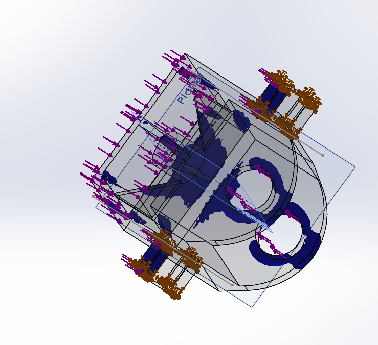
- images of the components are provided that show area where material can be removed.
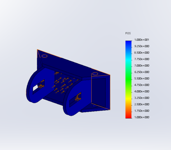
- furthermore, the prototype should a concern a different loading concern when it comes off of switching tracks, the force will not all be perpendicular to the track, so additionally FEA was done with different loading conditions.
- minimum Factor of safety = 27
- goals for next week
- start report
- Redesign my initial design of the "arm" for the guide arm,
- and hopefully have confirmed mounting points from interaction team.
Figure 1: The blue areas shows where most of the load is acting.
Figure 2: The transparent areas show where material can be taken off.
Figure 3: The loading was changed for this FEA study of the part.
Thursday, October 25, 2018
Week of 10/25/2018
10/25/2018 Akash Sandhu
For this week, we worked on 3D printing the design of the main component of the spring loaded guide arm. Pictures of the rapid prototype are provided below; the prototype is half-scale. From the damper calculations, I also contacted a possible vendor to obtain information about cycles/min. I also performed FEA on the last week's design, and changed dimensions so it can fit inside the 12 cm gap of the tracks. The parts has a low factor of safety, just above 1. I went back redesigned the wheel and spring holder. I relocated mounting points, add ribs, and increased material on the new design iteration. This increases safety factor to 2 for one component, and 10 for the other. Pictures are located below.


Thursday, October 18, 2018
Week 10/18/2018
Akash Sandhu 10/18/2018
Spring Loaded Guide Arm.
In preparing for the presentation I performed calculations for max load the spring needs to handle and spring rate. I also researched for the damper criteria need for damper selection. I research the the wavelength for roughness/straightness of light rail tracks. Then I went on to calculated the frequency need for the damper and the Max energy absorbed. The natural frequency of the guide arm assembly is much lower than the frequency of force given by the track. Looking at my calculated information for the damper Dr. Furman than concluded that the damper would not be practical or cost-efficient for the maker-faire model. Nevertheless, I will still continue designing for damper, but it will not be included in manufactured design. It was confirmed with the guide-way team that the track gap distance will remain the same at 12 cm. So currently, I am working to redesigning the whole design to be smaller using smaller wheels. While redesigning, I am taking into account my FEA results from previous design version. The plan is to 3d print the spring loaded component for rapid prototyping. Below I have attached some of the CAD designs and my MATLAB calculations.
ME 195a Spring loaded guide Arm calculations
Akash Sandhu
Contents
Force calculations
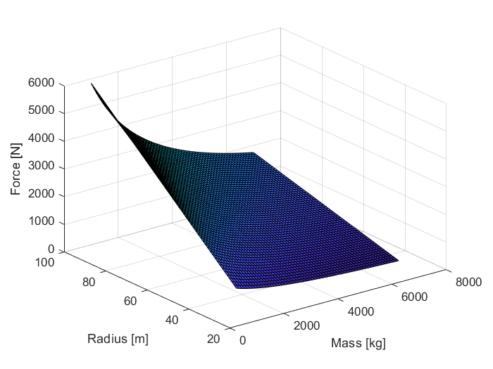
M = 500:100:7000; % kg, weight of whole bogie and loaded podcar total_length = length(M)-1; % v_min = 2; % v_max = 20; % dt_v = (v_max-v_min)/total_length; % % v = v_min:dt_v:v_max % m/s, operating speed of bogie v = 1 % m/s r_min = 8; r_max = 50; dt_r = (r_max-r_min)/total_length; r = r_min:dt_r:r_max; % m, smallest radius for i = 1:length(M) for j = 1:length(r) f(i,j) = 2*((M(i)*v^2)/r(j)); end end figure(1); surf(M,r,f); xlabel('Mass [kg]'); ylabel('Radius [m]'); zlabel('Force [N]'); title('Force vs Curvature and Mass');
v =
1

Spring Calculations
clear all; clc; M_tot = 2000 +300; %[kg] M_eq = M_tot/3; x = .13; % [m] v = 1; % [m/s] about 2 mph r = 8; %[m] radius of curve F = 2*((M_eq*v^2)/r); % [N] fprintf('The force acting on each spring is %1.3f N\n ',F) k = F/x; %[N/m] fprintf('The Spring rate is %1.3f N/m \n',k)
The force acting on each spring is 191.667 N The Spring rate is 1474.359 N/m
Damper (Shock Absorber) Calculations
F = 2*((M_eq*v^2)/r); % [N] M_tot = 2000 + 300; %[kg] pod + bogie M_eq = M_tot/3; % [kg] v_y = 13; % [m/s] speed going straight L = 0.016;% [m] stroke of damper theta_deg = 13; % [degree] angle of curvature theta = theta_deg*(pi/180); % [rad] v_x = tan(theta)*v_y; %[m/s] speed at impact FS = 2; % factor of safety E_1 = 0.5*M_eq*v_x^2; E_2 = F*L; E_tot = E_1+E_2; E_max = FS*E_tot; %[Nm] max energy absorbed fprintf('The max energy the damper needs to absorb is %1.3f Nm\n',E_max); wavelength = 0.05; %[m] irregularities observed at freq = v_y/wavelength; % [Hz] fprintf('The forcing frequency from the track irregularities will be %1.3f Hz\n', freq); freq = freq*60; % [ cycles/min] fprintf('The damper will need to be able to do %1.3f cycles/min\n',freq);
The max energy the damper needs to absorb is 6912.052 Nm The forcing frequency from the track irregularities will be 260.000 Hz The damper will need to be able to do 15600.000 cycles/min
Thursday, October 11, 2018
Week of 10/10/2018
Week of 10/10 Akash Sandhu
For this previous, I worked on some problems on the design I created. These problem came across when I trying running FEA. This week I fixed some mating issue I was having with the slot which would not allow me FEA. Furthermore, Dr. Furman had recommended, during office hours, to incorporated dampers into the guide arm, to reduce vibrations of the spring. This week I began looking at damper. However, I have come across two problem; I do not know exactly how the mounting hardware works for dampers, and I am trying to find the a way to do calculations to pick the correct damper. Also, I did some consideration of the forces that would be acting on the guide-arm wheels and spring, and Dr. Furman and I concluded only centripetal force needs to considered. I then went and created a MATLAB 3-D plot which is attached below. I was also able to complete the FEA on the part with 2000 N force to see area of concern. Lastly, the design is a little to big for the current with so I decided to go with smaller wheels to accommodate for the clearance problem; Nevertheless, now the design will change in dimension due to smaller wheels.
Subscribe to:
Posts (Atom)